


SwitChek is an automatic, insulation tester that is used to verify isolation switches / circuit breakers / electrical disconnects. SwitChek tests switches that are “off” to confirm that they provide effective electrical isolation. SwitChek provides non-electrical people with a simple and safe method of verifying electrical isolations before conducting mechanical maintenance.
SwitChek Insulation Test – Isolator Healthy
SwitChek Insulation Test – Isolator Faulty
SwitChek Insulation Test – Test initiates upon isolator opening
SwitChek Insulation Test – Remote reporting of Isolator Healthy
Features
Fast result
Press the “Test” push-button to commence insulation tester testing or install with connections for automatic insulation test initiation. Insulation test is completed in 10 seconds.
Clear result
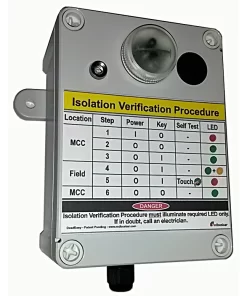
Green flashing LED = Safe isolation. Red flashing LED = Dangerous isolation. LEDs operate in positive mode. Confirmation cannot be confused with faulty LED.
Safe
Unlike visible blade isolators, SwitChek requires no viewing window in the switchboard or panel enclosure. So it does not compromise enclosure’s short circuit capacity.
Accurate
Automatic self calibration check before and after each switch test. SwitChek insulation tester is immune to internal and external connection faults, as the test result is not displayed if checks are not satisfied.
Universal application
SwitChek tests the isolating switch or circuit breaker by injecting a floating 500VDC test voltage on the supply side of the switch and monitors for DC current leakage on the load side of the switch. Testing can be performed on a switch or circuit breaker, thats line side, is either alive or dead ie energised or deenergised.
SwitChek is suitable for use on all 3 phase circuits. The cost of implementing visible break isolators increases substantially with circuit current rating.
Other Benefits
- Allows non-electricians to stress test an isolation switch.
- Test result is evident in bright, dark and dirty environments.
- Is a whole current, confirmation of isolation method.
- When housed in an Ex d enclosure, it is suitable for use in hazardous areas.
SwitChek Background
Electrical Isolation Procedures / Lockout Tagout (LOTO) Procedures often require that electrical switches be tested so as to confirm that the switch is “electrically off” once the equipment has been isolated. Confirmation or verification is often performed on the following isolating equipment:
- Isolation Switches
- Disconnects
- Circuit Breakers (CBs)
Typical Isolation Procedure testing methods include:
- Testing Dead or Test for Dead
- Attempt Start
- Observation of Visual Break Isolators (VBIs)
- Pilot lamp indication of energised phases
In many cases these isolation verification methods are complex, potentially misleading and expensive to perform. SwitChek exposes unsafe electrical isolations by detecting a failed isolation switch.
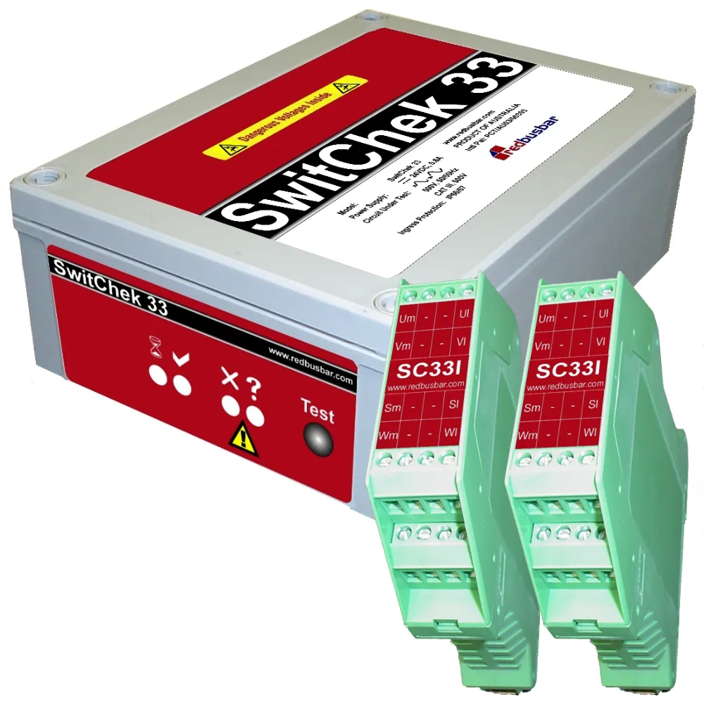
Package Includes
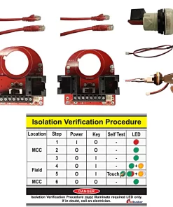
All the components necessary for one isolation switch / disconnect. Specifically:
- SwitChek Fixed Unit (SC33F)
- 2 off SwitChek Interface Modules (SC33I)
- Installation and operation manual
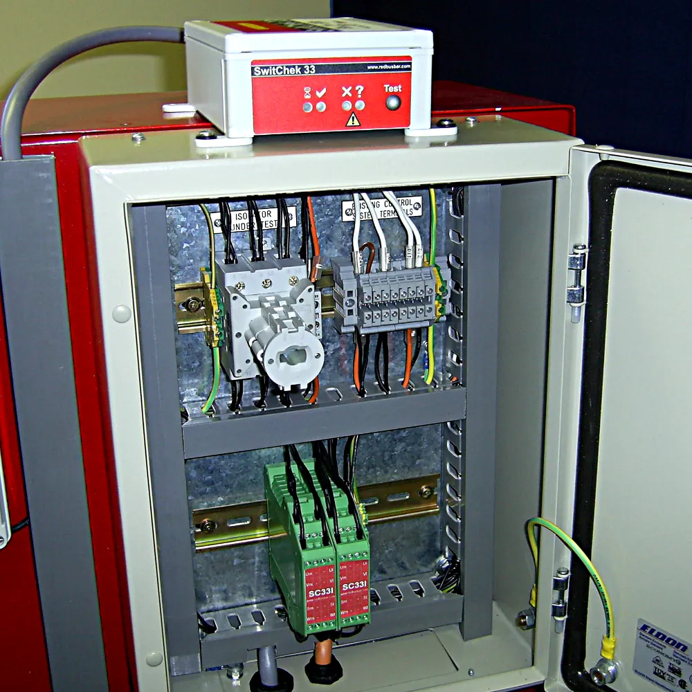
Excludes field panel shown in photo above.
Flyer Datasheet Interface Datasheet Installation & Operation ManualFAQ
Mainly because electrical isolations, even if the correct switch is turned off and locked, are not always sound.
We generally think that once we have turned off and locked an isolating switch or circuit breaker that the equipment is 100% safe to access. Not so, many, many switches from the largest manufacturers have failed in a mode that allows switches to pass current in the “off” position. The switch failures have caused fatalities in Australia and in the USA. The fatalities have motivated legislators towards the need to verify isolations. This legislation now requires isolation confirmation or verification of isolation. Many tests have been developed to test isolating switches. Some tests that are used today are cumbersome and some are potentially misleading.
Switch failure modes that allow the passing of current in the off position include:
- Welded switch contacts.
- Worn handles that fail to rotate the switch mechanism when the handle is rotated.
- Misaligned handles that fail to engage with the “handle to switch” connecting shaft.
- Switch bypass faults – cable-to-cable faults.
Perhaps there is a message in the fact that all major manufacturer’s of isolating switches now incorporate Visible Break Isolators (VBI) in their range!
SwitChek was designed to:
- Provide non-electrical people with a simple and safe method of verifying electrical isolations before conducting mechanical maintenance.
- Determine that a switch or circuit breaker, whether live or dead, is the Isolation Point.
- Provide operator confidence in the reported test result. The test approach adopted by SwitChek is identical to that performed by an electrician using an insulation resistance meter including the step of instrument self testing.
- Be a universal solution. SwitChek operates whether the conductors are electrically alive or dead and is not affected by electrically noisy environments.
Manual Isolation Testing using a high voltage test set (Megger) to report the fact that there is no passage, via the cabling in the circuit under test, between the line side and load side of the isolating switch. It tests both the switch and the connected cabling. However, if the line side of the switch is alive the person performing the test is at risk. In most cases the Megger is simply not rated to protect the person performing the test. Informed companies have recognised this exposure and test using a multimeter instead. Of course mutimeters do not generate a typical service voltage so they do not stress test the switch.
Yes, but only if you perform less than 1 isolation per month on an inpidual isolator. In this case the cost of purchasing SwitChek and installing a SwitChek Interface is more expensive than paying for an electrician to manually confirm an isolation. This cost comparison is quite conservative. What’s not included are the costs associated with maintenance/construction team waiting for the electrician to arrive. In addition, the cost assessment is based on the first year’s costs. Of course in the second and subsequent years SwitChek costs are negligible whilst manual confirmation of isolation costs are ongoing.
In summary, if you perform 1 isolation every month on an inpidual isolator, SwitChek payback is one year. Of course the cost assessment does not highlight which method of isolation confirmation is technically superior!
The “Attempt a Start” isolation procedure aims to determine, through the use of local or remote starting methods, that the isolation switch prevents the motor from starting. This is useful in allowing non-electricians to determine whether it is safe to perform mechanical maintenance on a motor e.g. grease bearings. The procedure for the “Attempt a Start” method is largely dictated by the facilities avalable for isolation and motor control and their locations.
The disadvantages of this approach are as follows:
- In most circumstnces the “Attempt a Start” method used does not actually stress test the isolation switch. In fact, it tends to prove that the control circuit is inhibited in someway eg emergency stop operated, incorrect mode (local/remote). The problem with this is is that it is the isolation switch that is locked. This means that later correct operation of the control circuit could reveal a faulty isolation switch with dangerous consequences.
- The “Attempt a Start” method often contains between 8 and 16 steps. Some of our clients believe that it is unrealistic to expect operational personnel to perform this procedure or even to perform it correctly on each and every occasion. In essence, they feel that a judge would see it this way also in the event of an accident.
- The procedure can be complex and it changes from plant to plant which makes it necessary to conduct special and regular training.
- The “Attempt a Start” method maybe inconvenient to use due to interlocks. That is, several other items may be required to start before starting the equipment of interest. Because of this arrangement confirming the isolation is sometimes abandoned.
This approach has been trialed before by our clients and generally takes the form of fixed pilot lamps that can be read by a non electrician. The thinking being that prior to initiating the isolation, all lamps are illuminated and after performing the isolation all lamps are extinguished. This result is interpreted as being a confirmed isolation.
The disadvantages of this approach are as follows:
- Poor pilot lamp to neutral connections yield shock voltages on the isolated side of a healthy switch. This point alone is reason enough not to pursue pilot lamps as it leads to potential electric shock situations.
- Using a strict testing approach, which is what is required when confirming an isolation, the approach to achieving a high integrity test result involves testing the lamps, testing the switch, testing the lamps = confirmed result. Clearly, when using pilot lamps, the last “testing the lamps” step can not be conducted without reversing the isolation or installing costly self-test circuitry. This defeats the purpose of the isolation in the first place! This scenario demonstrates how a blown lamp could yield an incorrect confirmation of isolation result.
- Lamps regularly fail due to vibration. Operating a switch handle causes significant transient vibration.
- Short lamp life when used on variable speed drive (VSD, VVVF) or soft starter circuits. Harmonic currents use the lamps as a path to earth which leads to failures within weeks.
- If the line side of the isolation point is dead, phase indication as a means of confirming an isolation cannot be performed.
If you need more convincing download a copy of the “Confirming Electrical Isolations” white paper on the Isolation Verification, Category page.
SwitChek provides greater testing flexibility than DeadEasy as it can conduct a test whether or not the line side of the switch is alive or dead. This is important for field isolators as the line side of the switch is most likely to be deenergised at the time of testing. DeadEasy requires the line side of the switch to be alive at the time of testing. As such it is most suitable for switchboard or motor control centre verification of isolation.
How can I install additional wiring to the load side of our circuit breakers, which are our isolation points, if we have close coupled contactor or overload units?
If you decide that proof of isolation is important to you and your company, you realistically have a choice of:
- Manual Testing.
- Visual Break Isolators.
- DeadEasy.
- SwitChek.
If you also decide that manual testing is too dangerous or cumbersome, then either Visual Break Isolators, DeadEasy and SwitChek require some modifications to your MCC (Motor Control Centre). Most switchgear manufacturers sell separate mounting kits for their contactors and Thermal Over Loads (TOLs).
This arrangement is supported by AS3000 so long as certain circuit conditions are complied with. AS3000:2000 Cl 2.4.4.4 requires that:
- The length of the circuit is less than 3m.
- The circuit has no branch circuits.
- The conductors are not located in the vicinity of flammable materials.
- The conductors are mechanically protected by being located in a metallic wiring enclosure.
The power cable and the SwitChek measurement cable should be crimped together in a single sleeve. The sleeve then fits easily into the switch tunnel terminal. In the case of larger power circuit conductors we recommend cable tieing “lip blade” terminals to the power circuit cable lugs.
Firstly, SwitChek is designed to withstand Cat III 600V installations in accordance with IEC 61010 . This means that it is suitable to withstand overvoltages sometimes experienced on 500V switchboards. The method for achieving this performance is by the use of sufficient creepage and clearance distances as well as using componentry certified to provide this level of protection.
Secondly, should an internal fault develop within SwitChek, the SwitChek Interface incorporates 1A, High Rupturing Capacity (HRC) fuses rated for installations up to 50kA fault levels. This means that the fuses will interrupt power to the fault prior to severe SwitChek damage.
Thirdly, SwitChek is contained in a double insulated, fire retardant, polycarbonate dust proof and water proof (IP66) enclosure. It is mechanically robust.
We know that SwitChek is costly to implement. However, if you decide that proof of isolation is important to you and your company, manual testing and Visible Break Isolator (VBI) approaches are generally more expensive.
Our suggestion is that you start by identifying the isolation switches in your plant that present the most risk to personnel. That is, the switches that:
- Are used to frequently isolate plant for maintenance, cleaning or inspection access, and switches that ….
- Isolate equipment that people climb into or major portions of their body are inserted into. That is, it has the potential to seriously injure or kill.
Start with providing a solution for these equipment items first. Alternatively, you risk becoming overwhelmed by the task at hand and doing nothing!
Whilst it has been a Legal requirement in Queensland, Australia since 1994 to confirm isolations on all equipment, the following equipment generally exposes the personnel to greater access (hence exposure to severe injury or death) when being maintained:
- Printing Press.
- Jaw Crusher.
- Wood Chipper.
- Cut-off Saw.
- Conveyor.
- Forging Machine.
- Ball Mill.
- Ribbon Blender.
To our knowledge, no one! SwitChek is Patented.
No. The power supply to the Portable SwitChek requires a hardwired interlock from the panel mount, female socket connection. Therefore, no dangerous voltages will appear at the plug pins whilst the plug is not plugged into a SwitChek Interface Connector.
No. The test voltage generated is floating with respect to earth. The voltage is applied across the switch. The test voltage is applied line side with respect to load side. However, if for example a worker was in direct contact with the wires and earth downstream of the isolation switch that incorporates SwitChek, and the AC supply system has an earth reference (common arrangement), the worker would receive a tingle for one second if the test pushbutton was pressed. The tingle current would be a maximum of 3mA which for some people is below their threshold of perception. In summary, there is no danger upstream or downstream to personnel, VSDs or other equipment as they see no potential difference between phases or appreciable shock current with respect to earth.
Potentially, yes but not likely. This would need to be considered for your installation. The SwitChek Interface socket penetration is approximately 35mm in diameter. This translates to a penetration a little larger than approximately 1 x 30.5 pilot indicator light. This is certainly a better arrangement than multiple pilot lights or a window for a Visible Break Isolator (VBI).
SwitChek has undergone rigorous laboratory and field testing. It has demonstrated 100% reliability during all tests. SwitChek has been developed as a safety device to meet the requirements of a SIL 1 Control System as per AS61508.1 Functional Safety of electrical/electronic/programmable electronic safety-related systems. In principle, this means that a single fault within the test system will not impede the safety function and will be detected and indicated to the user. What this means is that SwitChek will have a long life span typical of all electronic equipment. However, if it should fail it will indicate that the test is invalid because of the failure and that the operator will not be placed at any risk. It will not indicate a “Pass” when in fact the switch is faulty or closed.
The simplistic view is that SwitChek performs a stress test on a switch. This consumes approximately 3 seconds of a 10 second test cycle. The remaining 7 seconds are spent validating the integrity of the SwitChek and the SwitChek Interface. For instance SwitChek identifies the following faults as a “SwitChek Fault”:
- Insufficient stress test voltage.
- Failure to inject stress test voltage.
- Failure to determine healthy connection of the SwitChek Interface. Wire broken/fuse blown.
- Failure to measure internal calibration impedance within upper and lower toleraces.
- Failure to measure internal SwitChek disengagement impedance within upper and lower toleraces.
- Low SwitChek power supply voltage.
Using a microcontroller as the engine of SwitChek has allowed extensive testing of SwitChek. Three thousand consecutive tests were successfully completed followed by a single closed isolator test that reported an isolator fail condition. Of course, operators can gain confidence in the use of SwitChek by simply closing the isolating switch and performing a test. SwitChek will report a “Fail” under this circumstance.
You should treat the panel mount socket terminals as alive. However, the touch proof (IP21), recessed socket pins connect to the star point of a resistor bank located in the SwitChek Interface. This means that under normal conditions, only the out of balance voltage appears at the pins of the socket which is typically less than 10V on a 415VAC system. In addition each leg of the resistor bank incorporates a 1A fuse and two 100KOhm resistors in series. This means that it has the capability of delivering up to 1.2mA at 240VAC in the event of a faulted leg in the resistor bank. A faulted leg in the resistor bank will be detected the next time SwitChek executes a test. This means that it is highly unlikely that someone could be exposed to an electric shock from the panel mount socket.
If I install SwitChek do I need need to Test for Dead before performing electrical maintenance?
Yes. In fact, testing for dead is a legal requiremnet in most jurisdictions. There are however good reasons why you should not rely on it to verify an isolation in some cases.
If you need more convincing download a copy of the “Confirming Electrical Isolations” white paper on the SwitChek page.
Anyone. If you can press a button and read an indication light you can operate SwitChek. No licenses are necessary.
Documents
Installation Drawings
Download … Single Line Diagram (PDF)
Download … Termination Diagram (PDF)
| Weight | 1.5 kg |
|---|---|
| Dimensions | 30 × 25 × 15 cm |
Related products
Isolation Verification
Reviews
There are no reviews yet